
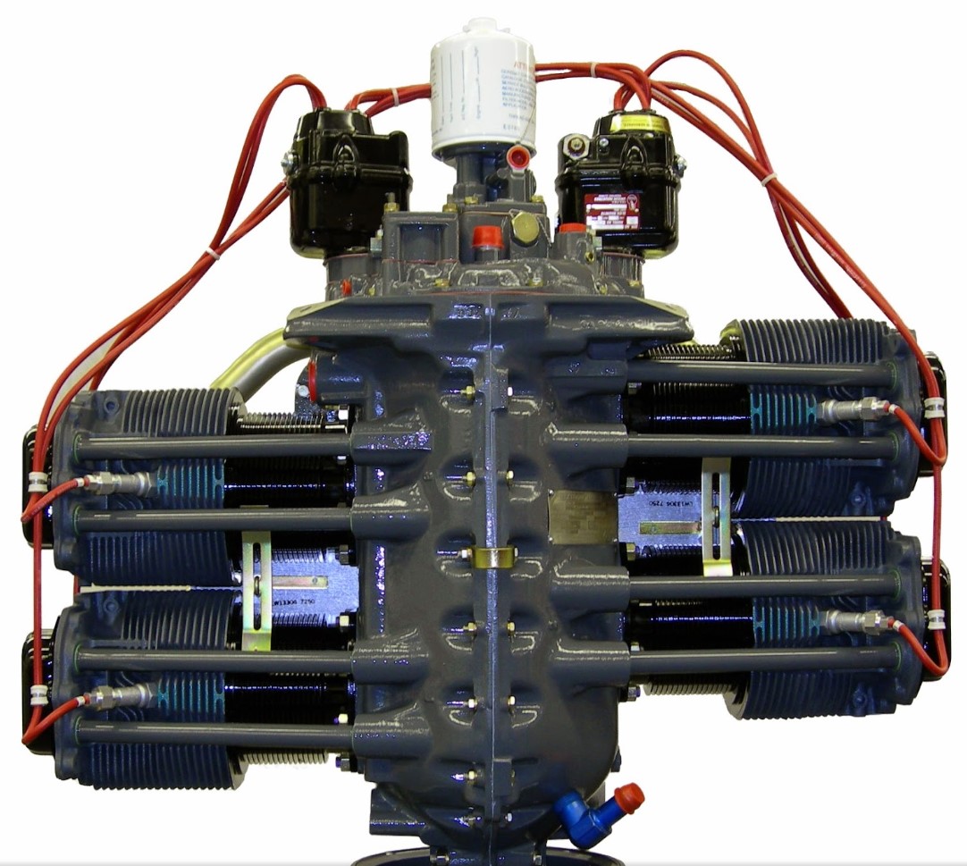
All of our tugs are fitted with a Lycoming 0-360 series aircraft engine, which is a four cylinder, wet sump, horizontally opposed, air cooled engine. The cylinders are not directly opposite from one another but are staggered, thus permitting a separate throw on the crankshaft on the crankshaft from each connecting rod.
Two variants are currently in use, the O-360-A3A and the O-360-A3M. The A3A engine has a hollow crankshaft whilst the A4M has a solid crankshaft. The A3A engine usually has a restricted rpm band when a metal propeller is fitted. The A4M engine has no such restriction but weighs approximately 3kgs more.
Cylinders
The cylinders are of a conventional air-cooled design with two major parts, head and barrel, screwed and shrunk together. The heads made from aluminium alloy casting with a fully machined combustion chamber. The cylinder barrel, which is machined from a chrome nickle molybdenum steel forging with deep integral fins, is ground and honed to a specific finish. The valve rocker shaft bearing supports and the rocker box housing are cast integrally with the cylinder head.
The valves are cooled by means of fins which completely surround the area of the exhaust valve and portions of the intact valve. A sodium-cooled rotator exhaust valve is employed on this engine. Bronze valve guides and austenitic chrome nickle steel valve seats are shrunk into the machined recesses in the head.
Valve Operating Mechanism
The valve operating mechanism is located on the top side of the engine, facilitating proper lubrication and easy accessibility. The camshaft is located parallel to and above the crankshaft and operates aluminium bearings. The camshaft in turn actuates the valves by means of mushroom type hydraulic tappets, which automatically keep the valve clearance to zero. The valve rockers are supported on a full floating steel pin. The valve springs bear against both upper ad lower steel seats and are retained on the valve stems by means of split keys.
Crankshaft
The crankshaft is made from chrome nickle molybdenum steel forging. All bearing journal surfaces are nitride hardened and centrifugal sludge removers are provided in the form of sludge tubes at each crankpin journal. These tubes can be easily removed and must be replaced at overhaul of the engine.
Crankcase
The crankcase assembly consists of two reinforced aluminium alloy castings divided vertically at the centreline of the engine and fastened together by means of through bolts and nuts. The mating surfaces of the crankcase are joined without the use of a gasket and the main bearing bores are machined for use of precision type main bearing inserts.
Oil Sump
The oil sump incorporates an oil screen filter, carburettor mounting pad, the intake riser and the intake pipe connections. The fuel-air mixture passes through the riser, is vaporised by the heated oil in the sump that surrounds the riser. The carburettor mounting pad is located on the bottom of the sump on all models except those incorporating a horizontal draft carburettor. On these models the carburettor mounting pad is located on the rear of the sump.
Connecting Rods
The connecting rods are made in the form of “H” sections from alloy steel forgings. They have replaceable bearing inserts in the crankshaft ends and bronzes bushings in the piston ends. The bearing caps on the crankshaft ends of the rods are retained by means of two bolts and nuts through each cap.
Pistons
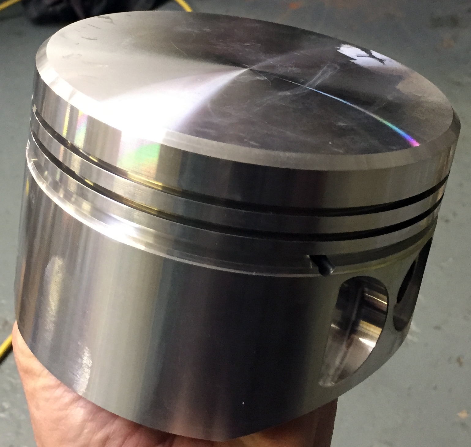
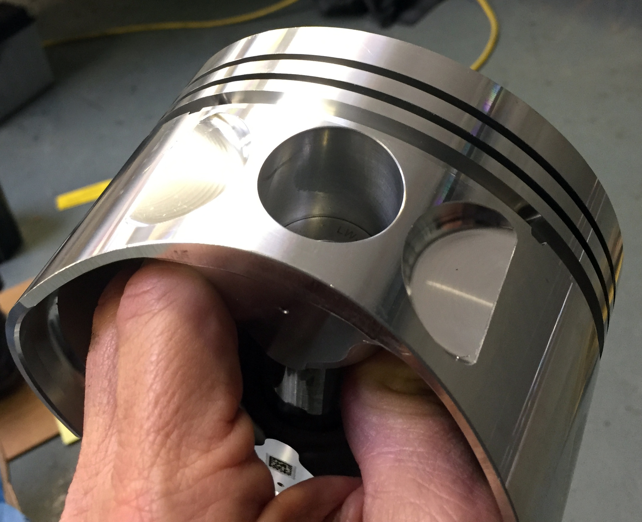
The pistons are machined from an aluminium alloy. Earlier models and all low compression series incorporate two compression rings and one oil regulator ring while later models of the high compression series incorporate three compression rings and one oil regulator ring. The piston pin is of the full floating type with an aluminium plug located in each end to prevent the pin from touching the cylinder wall.
Accessory Housing
The accessory housing is made from an aluminium casting and is fastened to the rear of the crankcase and the top rear of the oil sump. It forms a housing from the oil pump and various accessory drives.
Gears
The gears are of the conventional type and are precision machined. They are hardened to ensure long life and satisfactory operating qualities.
Cooling System
The air pressure cooling system is actuated by the forward speed of the aircraft. Baffles are provided to build up air pressure between the cowling and the top of the cylinders, thus forcing the cool air down through the cylinder fins. The air is then exhausted through the rear of the lower cowling.
In our operation it is most important that the baffles and fit of the cowling stay in good condition for efficient cooling. Also, pressure cooled engines can overheat on the ground at idle power, so idling should be kept to a minimum and wherever possible carried out with the aircraft pointing into wind.
Lubrication System
The lubrication system is of the pressure wet sump type. The main bearings, connecting rod bearings, camshaft bearings, valve tappets, push rods and crankshaft idler gears are lubricated by positive pressure. Piston pins, gears, cylinder walls and other parts are lubricated by means of oil collectors and sprays. The oil pump, which is located in the the accessory housing, drawers oil through a drilled passage leading from the oil suction screen located in the sump. The oil from the pump enters the drilled passage in the accessory housing, which feeds the oil to a threaded connection on the rear face of the housing, where a flexible hose leads to an external oil cooler. In the event that cold oil or an obstruction should restrict the flow of oil to the cooler, an oil cooler by-pass valve is fitted. Pressure oil from the cooler returns to a second threaded connection on the accessory housing below the tachometer drive.
The oil pressure screen is provided to filter from the oil any solid particles that may have passed through the suction screen in the sump. After being filtered in the pressure screen chamber, the oil is fed to the pressure relief valve, located in the upper right side of the crankcase in front of the accessory housing.
The oil relief valve regulates the engine oil pressure by allowing excessive oil to return to the sump, while the balance of the pressure oil is fed to the main oil gallery in the right half of the crankcase. During its travel through the main gallery, the oil is distributed by means of separated drilled passages to the main bearings of the crankshaft. The drilled passages to the bearings are located in such a manner as to form an inertia type filter. Thus, only the cleanest oil will be fed to the main bearings. Separate passages from the rear main bearing supply pressure oil to both crankshaft idler gears. Angular holes are drilled through the main bearings to the rod journals where sludge removal tubes are located. Here centrifugal force of the crankshaft removes any heavy sludge that maybe present in the oil. Oil from the main oil gallery allows flows to the cam and valve gear passages, and is then conducted through branch passages to the hydraulic tappets and camshaft bearings. Oil enters the tappets through indexing holes and travels out through the hollow push rods to the valve mechanism, lubricating the valve rocker bearings and valve stems. Residual oil from the bearings, accessory drives and the rocker boxes is returned by gravity to the sump, where after passing through a screen it is again circulated through the engine. Pressure build build up within the crankcase is held to a minimum by means of a breather located on the accessory housing.
Induction System
The engines used in the tugs are equipped with a Marvel-Schebler Model MA-4-5 carburettor. This carburettor is of the single barrel float type, and is equipped with a manual attitude mixture control and an idle cut off. It is mounted in the standard updraft position on the bottom of the sump. Particularly good distribution of the fuel-air mixture to each cylinder is obtained by the centre zone induction system, which is integral with the oil sump and is submerged in oil, ensuring a more uniform vaporisation of fuel and aiding in cooling the oil in the sump. From the riser the fuel-air mixture is distributed to each cylinder by separate steel intake pipes.
Ignition System
Dual ignition is furnished on the O-360 series engines by two magnetos. The ignition wiring is so arranged that the left magneto fires the top plugs on the left bank and the bottom plugs on the right bank, while the right magnetos fire the top plugs on the right bank and the bottom plus on the left bank. This arrangement ensures consistent drop off when switching from both magnetos to either the right or left magneto. The engine fire order is 1-3-2-4.
Return to ‘Aircraft’ Return to ‘Front Page’