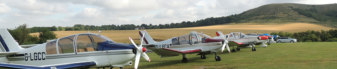
On all aircraft most of the blind flying and navigation equipment is disabled by circuit breaker or may be unserviceable, and is generally deemed unnecessary for our operation. Likewise you may find navigation and landing lights inoperative. The main differences are to be found on the Instrument Panels, shown below.
G-LGCA

CA Differences
- Key Ignition. The starter motor is actuated by turning the key right against spring pressure. Whilst in the position the Right Magneto is isolated.
- Anti Collision comes on with the Master Switch and is controllable only by Circuit Breaker.
- There is an ELT unit visible but not functioning.
- A turn indicator is fitted though not functioning.
- Trig TT31 Transponder fitted. Operating instructions can be found here and the detailed manual here.
- Left Side throttle removed.
G-LGCB
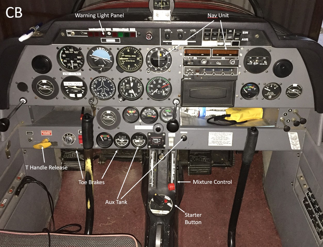
CB Differences
CB is structurally different in that the panel and coaming is deeper, behind the “higher than normal” engine cowling. You should consider a cushion to increase visibility.
Other Differences;
- Toe operated wheel brakes.
- ‘T’ Handle tow rope release. Operates between 10 and 15 cm extension.
- Starter Button located next to Fuel Cock, hidden when Fuel Cock closed.
- Auxiliary Fuel Tank fitted.
- Combined NAV/COM unit fitted.
- High coaming which includes Warning Light Panel and Switches.
G-LGCC

CC Differences
- Pilot Headphone sockets located on front panel below radio.
- Digital CHT gauge fitted. Select 3 or 4, the rearmost and hottest cylinders.
G-BVYM

YM Differences
YM is a DR300 aircraft and has a narrower fuselage (approx 100mm) on the same Robin wing. This results in a narrower cockpit and a slight increase in wing area enabling this aircraft to fly slightly slower than it’s DR400 counterparts. The other main difference is the ‘gull wing’ canopy and rather fiddly catchments.
- Different canopy and catches.
- Master Switch is a push/pull knob.
- Trim indicator and actuator mounted on panel.
- Alternator is operated by a simple switch.
- Auxiliary Fuel Tank fitted.
Auxiliary Fuel Tank (CB & YM) – Operation
If the auxiliary fuel is used. The main fuel tank should be depleted to half or less, operate the Aux Fuel tank valve by pulling the actuating knob fully out. This will allow Aux tank fuel to flow into the main tank and effectively “refuel” it. Fuel for the engine driven fuel pump and the electrical fuel pump is drawn from the main tank only.
Note: For normal operations the Aux tank will remain empty. You may notice a small amount showing on the Aux tank gauge, this is normal as we keep a litre or two of fuel in the tank to keep the seals lubricated. Don’t operate the valve to deplete this fuel.
Return to ‘Robin Operations‘ Return to ‘Operations’ Return to ‘Front Page‘